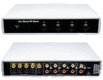
4-х канальный AV селектор
Каждый раз, когда Вы хотите переключиться между DVD, видеомагнитофоном, игровой приставкой и видеокамерой, вы должны переключать аудио/видео (A-V) кабель вашего телевизора. Если так, этот проект решит эту проблему. Это позволяет Вам выбирать любое из четырех S-видео или других видео источников и также переключает сопровождающий аудио стерео или bitstream цифровую звукозапись.
ЕСТЬ МНОГО A-V селекторов, доступные и имеющийся в наличии, но это - дешевый модуль, который Вы можете собрать самостоятельно. Просто собрать, и Вы больше не будете постоянно переключать A-V кабеля,когда захотите сменить видео источник.
Модуль обеспечивает переключение 4-х каналов и для S-видео и для композитных видео источников, но почему бы не предусмотреть составляющее видео и RGB? И почему мы не учитывали переключение аудио 5.1 каналов или даже с 7.1 каналами, вместо того, чтобы согласиться только на Стерео или цифровой bitstream аудио?
Есть простой ответ с одним словом на эти вопросы: стоимость. Если бы мы обеспечили те дополнительные опции, то сложность схемы росла бы значительно.
Короче говоря, должен был быть компромисс между обеспечением всех возможномтей, которые любой мог бы желать и создание привлекательной конструкции для так многих людей насколько возможно.

Комутация звука
Точно так же мы решили не беспокоиться о коммутации звука с 5.1 или 7.1 каналами аналоговом аудио, потому что в большинстве случаев эти объёмные каналы должны быть декодированы системой Dolby Digital / AC-3 или DTS (digital surround). Этим декодером снабжены большинство DVD проигрывателей. Так как цифровые декодирующие устройства встраиваются в surround-sound усилители (и обычно лучше чем декодирующие устройства, встроенные в DVD плеер), нет никакой необходимости производить декодирование и разделение аналоговых сигналов звуковой частоты.
Фактически, мы полагаем, что этот компромисс обеспечивает селектор таким образом, что он удовлетворит потребности большого числа людей.
Как это работает
Наш Четырехканальный A/V селектор действительно очень прост. По существу, это - только переключатели четырех каналов, с двумя полюсами, переключающими видео для каждого канала и стерео аудио.
Единственная причина мы фактически не используем механический выключатель с 4 позициями. Вместо этого мы используем восемь миниатюрных реле DPDT - четыре, чтобы переключить видео сигналы и четыре, чтобы переключить аудио. Эти реле управляются отдельными схемами драйвера, в свою очередь которыми управляет одна из четырех кнопок.
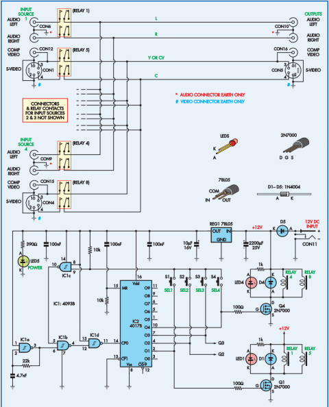
Схема четырехканального селектора показана на Рис.1. Сигнал, переключающий схему в верхнее положение, использует одно реле, чтобы переключить два звуковых канала для каждого источника A-V и secondrelay toswitch видео сигнал (то есть, Y и S-видео Cfor или композитный видео сигнал). В этом случае, реле 1 и 5 переключают сигналы для Источника 1, в то время как реле 4 и 8 переключают сигналы для Источника 4.
Работа четырех реле (для Источников 2 и 3) иакая же, но пропущено в целях упрощения схемы.
Катушки для каждой пары реле соеденены параллельно и управляются транзисторами 2N7000 MOSFETs (Ql и Q4). Однако, только Ql и Q4 показывают на схемном решении, снова для простоты.
Остальная часть схемы выполняет выбор один из четырех каналов. Это основано только на двух дешевых CMOS микросхемах: 4093B - четыре элемента И-НЕ (ICl) и 4017B - десятичный счетчик (IC2).
IClа работает как генератор выбора, работающий приблизительно на 20кГц. Его вывод 3, через элементы IClb и ICld подается на счетный вход 14 десятичного счетчика (IC2).
В исходном состоянии, микросхема IC2 сброшена конденсатором 100nF и резистором 10k, ни одно реле не включено.
При нажатии кнопки S1, логический 0 поступает на IC1c, который разрешает работу генератора через элементы IC1b и IC1d.
Счетчик начинает отсчитывать импульсы, и как только на выводе 2 (IC2) появится логический 1, схема остановится.
Логический 1 (с вывода 2 IC2) через резистор 100 Ом откроет транзистор Q1, сработают реле и загорится светодиод LED1.
Диоды D1-D4 защищают транзисторы от обратной ЭДС.
Рис.1: схема использует восемь миниатюрных реле DPDT четыре, чтобы переключить видео сигналы и четыре, чтобы переключить аудио. (нажмите на рисунок для увеличения)
Список деталей
1 плата, размер 198 x 157mm
1 корпус, размер 225 x 165 x 40mm
5 двойных RCA гнезда (аудио)
5 мини 4-pin DIN sockets (S-Video)
5 RCA , желтые
1 2.5mm разъем - питание
4 кнопки SPST
8 реле DPDT 12V
10 6шт x 6mm - самонарезные винты
1 Источник 12V 150mA постоянного тока
Полупроводники
1 HEF4093B четыре элемента И-НЕ (IC1)
1 4017B Десятичный счетчик (IC2)
1 стабилизатор 78L05 5V (REG1)
4 транзистора 2N7000 (Q1-Q4)
4 3mm красных светодиодов (LED1-LED4)
1 3mm зеленый светодиод (LED5)
5 диодов 1N4004 400V 1A (D1-D5)
Конденсаторы
1 2200µF 25V электролитический
1 10µF= 16V электролитический
2 10OnF многослойный монолитный
1 100nF полиэстер MKT
1 4.7nF полиэстер MKT
Резисторы (0.25W 1
1 - 22 kОм 1 - 390 Ом
2 - 10 kОм 4 - 100 Ом
4 - 1 kОм
Источник питания
Для питания необходимо напряжение 12V постоянного тока силой 150mA, штепсель снабжен диодом D5, обеспечивающий защиту от обратной полярности. В качестве фильтра +12VDC используется электролитический конденсатор 2200µF 25V.
+12V также питает стабилизатор напряжения REG1, который обеспечивает микросхемы ICl и IC2 напряжением +5V. Этим напряжением также питается светодиод LED5 через токоограничивающее сопротивление 390 Ом, для индикации напряжения питания.
Construction
A single-sided PC board measuring 198 x 157mm (EPEcode 676) accommodates most of the circuitry. This fits snugly inside a standard low profile plastic instrument boxmeasuring 225 x 165 x 40mm, with all of the audio, video and power connectors accessed from the rear panel. The selector buttons and LEDs are mounted on the front panel.
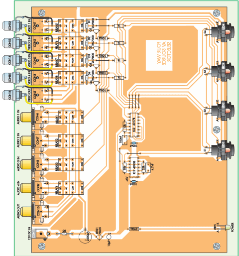
The component layout and wiring details are as shown in Fig.2. Begin construction by fitting the 11 wire links, then fit the five dual RCA phono sockets (CON6 to CON10) to the rear of the board. Make sure that these socket assemblies are pushed all the way down onto the board and that their plastic locating spigots go through their matching holes before soldering the pins.
Follow these with the DC input connector (CONll) and the five mini-DIN connectors (CONl to CONS). Once again, make sure that these connectors are all properly seated before soldering them.
The next step is to fit eight PC board terminal pins, which are later used to terminate LEDs 1 to 4. These pins go along the front of the board, in the positions marked A and К on Fig.2 (ie, on either side of each pushbutton switch).
That done, cut four 25mm lengths of tinned copper wire and bend each one into a U-shape, with the arms about 5mm apart. These should then all be fitted in the positions shown for the connections to switches Si to S4. Solder their ends to the pads underneath, then cut each U-shaped loop at its top centre and straighten the ends, to form a pair of wires ready to connect to the switch lugs.
Next, cut five 35mm lengths of yellow hookup wire and another five 35mm lengths of black hookup wire and remove 4mm of insulation from both ends of each piece. That done, solder one end of each of these wires to the PC board, as shown in Fig.2 - these are later used to connect the composite video connectors (CON12 to CON16) to the PC board.
The eight mini DIL relays are next on the list, followed by the 12 resistors, the two lOOnF multilayer monolithic capacitors (small and usually blue) and the two MKT polyester capacitors. These parts are all non-polarised, so they can be fitted either way around.
By contrast, the 2200(iF and 10(iF electrolytics are polarised, so be sure they go in the right way around. Fit these now, then install diodes D1-D5, again making sure they are correctly orientated. Diodes Dl to D5 have their cathodes (K) indicated by a band on their body. The LEDs have a flat on theirpackage against the cathode lead; also the anode (A) lead is longer.
Final board assembly
The PC board assembly can now be completed by installing the 78L05 regulator (REG1), transistors Ql to Q4, the two ICs and LED5. MOSFETs Ql to Q4 and REG1 all come in 3-pin TO-92 packages and must be orientated as shown (don't get them mixed up). Similarly, the two ICs (both CMOS devices) must be correctly oriented.
Be sure to observe the usual precautions when handling the CMOS devices - ie, use an earthed soldering iron, make sure you're not carrying a charge yourself, avoid touching the pins and solder the supply pins to the board first (pins 7 and 14 for ICl and pins 8 and 16 forIC2).
The green LED (LED5) is fitted to the board at full lead length, with its longer anode (A) lead to the left. Once it's in, bend both leads forwards by 90° about 10mm above the board. This will position the LED so that it will protrude through a matching hole in the front panel.
Рис. 2: следуйте этому рисунку при сборке 4-х канального селектора.
(нажмите на рисунок для увеличения)
Casing up
The drilling details and dimensions for the specified low-profile case is indicated in Fig.3. Use the front and rear panel artworks as drilling templates (or use the drilling diagrams), [ust attach copies of the artworks to the panels and drill and ream the holes to suit. These panels are reproduced here full-size.
Once the panels have been drilled, you can prepare the labels by glueing the artworks onto adhesive-backed A4 label paper. The stickers can then be covered with clear packaging tape to protect them, before cutting to size.
After that, you just peel off the backing tape, carefully affix each one to its panel and cut out the holes using a sharp hobby knife.
The next step is to cut away the three moulded PC board support pillars in the bottom half of the case, near the centre of the rear edge. This is necessary so that they don't interfere with the solder joints on the connectorpins. The plastic is quite soft and it's easy to cut away the redundant pillars with a pair of sharp side cutters.
That done, fit the rear panel over the dual RCA phono connectors on the PC board and lower the assembly into the case. The PC board can then be secured to the base of the case using five 6mm-long self-tapping screws, which go into the integral mounting pillars - see Fig.2.
Now use the remaining five 6mm self-tapping screws to fasten the rear panel to the five dual RCA phono sockets (CONG to CON10). These screws go through the panel and into matching holes in the connector bodies, so the operation is quite straightforward. The five single RCA sockets (CON1 to CON5) can then be fitted to the panel (above the mini-DIN sockets), with the supplied earthing solder lugs under the nuts and oriented upwards.
Tighten each nut using a small spanner or pliers, then bend the free part of the lug forwards by about 75°. Finally, solder the yellow wires to the centre terminals of the sockets and the black wires to the earth lugs.

Front panel
The front panel assembly is even easier - just mount the four pushbutton switches (Si to S4) but don't over-tighten the large plastic nuts provided, as it's easy to strip their threads if too much force is applied. Note that each switch should be positioned so that its terminals are aligned horizontally, for easy connection of the wires from the PC board.
That done, lower the front panel into its slot in the bottom of the box and solder the switch leads to their matching wires. A word of warning here: make each solder joint as quickly as possible, so that you don't overheat the switch or risk melting the solder at the lower end of each wire.
Finally, push the green power LED (LED5) through its matching hole and install the four channel indicator LEDs {LEDs 1 to 4). The latter are simply pushed through their respective front panel holes and their leads soldered to the PC stakes.
It's a good idea to bend each LED's leads to its approximate shape before trying to fit the LED in position. You do this by first bending the leads outwards by 70° about 8mm from the back of the LED body, then bending them downwards by 90° about 6mm out from the first bends (see photo).
Be sure to install them the right way around - the longer anode lead goes to the left PC stake in each case (see Fig.2).
The soldered connections should be sufficient to hold the LEDs in place. However, you may also want to apply a small 'dab' of epoxy cement to the rear of each LED, to make them a little more secure.
Your Four-Channel A-V Selector is now complete and ready for testing.

Проверка
Методика испытаний проста. Все, что Вы должны сделать, подключить питание к CON11, используя 12V постоянного тока, и проверить, что блок работает правильно.
Во-первых, проверяют индикацию напряжения питания, зеленый индикатор напряжения. Если он горит, нажимают одну из кнопок. Красный индикатор выше той кнопки должен немедленно загореться, и Вы должны услышать слабый стук, из-за переключения двух реле для того канала.
Теперь нажмите одну из остальных кнопок. Его индикатор должен загореться и должен быть услышан другой слабый стук, который активирует реле канала, и ранее активизированные реле выключают.
Наконец, нажмите одновременно две кнопки и проверьте, что Вы получаете ту же самую реакцию. Если так, Ваш 4-х канальный Селектор A-V работает правильно, и Вы можете теперь закрыть его верхней крышкой, используя четыре винта M3 x 25.

Устранение неисправностей
В этой схеме мало блоков, которые могут работать не так как надо. Однако проблемы могут возникнуть из-за неправильного подключения поляризованных деталей (диодов, электролитических конденсаторов и т.д.).
Если не работает вся схема, то вероятно, что Вы или подключили диод D5 в неправильном направлении к 2.5-миллиметровому штепселю на 12V или спутали полярность батареи питания. Если контур работает правильно, но один из этих пяти индикаторов не горит, то Вы спутали полярности светодиода при подключении.
Reproduced by arrangement with
SILICON CHIP magazine 2008.
wwvv.siIiconchip.com.au
Everyday Practical Electronics, August 2008



Перевод корявый...
Третий раз этот вопрос задаю
Нажимаем кнопку S1. В этот момент на выходе 2 IC2 лог.0. Перекувыркнувшись, лог.1 подается на элемент IC1b, таким образом, разрешив прохождение импульсов. После того, как счетчик дощелкает до вых.2, на нем появится лог.1. Опять же, после IC1c будет лог.0, которая прикроет IC1b? и импульсы перестанут проходить.
Цитата:
через нажатую кнопку