Многоуровневый датчик воды
Если у вас есть бак для сбора воды, то всегда хочется знать , сколько же там воды?
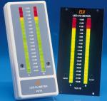
Наш многоуровневый датчик покажет 10 уровней заполняемости бака.
Датчик - двухпроводный.
Raising the bar
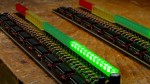
That's where this simple circuit comes in. It uses a row of ten coloured LEDs arranged in a bargraph display to give a clear indication of how the water supply is holding up. The more LEDs that light, the higher the water in the tank.
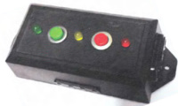
The LEDs are arranged in the familiar 'traffic light' colours of green, yellow and red to instantly indicate relative levels at a glance (green is good, yellow not so good and red is a warning) as well as the specific levels represented by the individual LEDs.
A further red LED lights when the tank level drops below a critical threshold. This can simply be to warn you of impending localised drought (hey, your tank's empty!) - or it (or indeed any of the ten-LED 'string') could be used to trigger an audible alarm or turn on a pump, as we will discuss later. There are no fancv microcontrollers or digital displays used in this project. Instead, it uses just a handful of common parts to keep the cost as low as possible.
It can be used in virtually any type of tank. As long as you can get access inside the tank from the top to the bottom, this circuit will work.
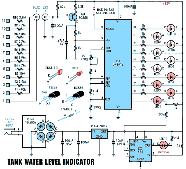
Fig.1. the circuit is essentially a bargraph display, calibrated so that appropriate LEDs light up as the sensors are covered by the rising tank water level. The 555 timer triggers another LED when the water level falls to critical.
Circuit description
The circuit diagram for the Tank Water Level Indicator is shown in Fig.l. It is based on an LM3914 linear LED dot/bar display driver (ICl) which drives tenLEDs (LEDsl to 10).
Pin 9 of the LM3914 is tied high so that the display is in bargraph mode and the height of the LED column indicates the level of the water in the tank. However, this pin can be easily isolated, turning the display into a dot type, thus saving power. If you're running from a battery supply in your garden, then every milliamp is precious.
Indeed, the PC board pattern has been arranged so that a miniature switch could be included to swap between bar and dot modes.
The full-scale range of the bargraph depends on the voltage on pin 6. This voltage can be varied using preset VR1 from about 1.61V to 2.36V. After taking into account the voltage across the 390ftresistor on pin 4, this gives a full-scale range that can be varied (using VR1) between about 1.1 V (VR1 set to Oft) and 2V (VR1 set to 470ft).
If you're wondering where all the above voltages came from, just remember that ICl has an internal voltage reference that maintains 1.25V between pins 7 and 8. This lets us calculate the current through VR1 and its series lkft resistor, and since this same current also flows through the series 1.5kft and 390ft resistors, we can calculate the voltages on pins 6 and 4.
As well as setting the full-scale range of the bargraph, VR1 also adj usts the brightness of LEDs 1 to 10 over a small range. However, this is only a secondary effect - it's the full-scale range that's important here.
ICl's outputs directly drive LEDs 1 to 10 via lkft current-limiting resistors. We have used the full 10 outputs of the chip to obtain a more accurate level indication.
If you only want five levels, you could omit LEDs 2, 4, 6, 8 and 10 and tie pin 11 to pin'lO, 13 to 12,15 to 14,17 to 16 and 1 to 18. In this case we'd use two green, one yellow and two red LEDs in the bargraph.

Water level sensor
The input signal for ICl is provided by an assembly consisting of 11 sensors located in the water tank and connected to the indicator unit via lmht-dutv figure-8 cable. This sensor assembly relies on the fact that there is a fairly low (and constant) resistance between a pair of electrodes in a tank of water, regardless of the distance between them.
Every school child is taught that pure water is an insulator. This circuit demonstrates the fact that even rain water is not exactly pure.
As shown in Fig.l, sensor 1 is connected to ground (0V), while sensors 2 to 10 are connected in parallel to the base oiPNP transistor Ql via resistors Rl to RIO. Transistor Ql functions as an inverting buffer stage and its collector voltage varies according to how manv sensor resistors are in-circuit (ie, how many sensors are covered by water).
When the water level is below sensor 2, resistors Rl to RIO are out of circuit and so Ql's base is pulled high by an 82Ш resistor. As a result, Ql is off and no signal is applied to ICl (therefore, LEDs 1 to 10 are off).
However, if the water covers sensor 2, the sensor end of resistor Rl is essentially connected to ground. This resistor and the 82Ш resistor now form a voltage divider and so about 9.6V is applied to Ql's base.
As a result, Ql's emitter is now at about 10.2V, which means that 0.8mA flows through the 2.2Ш emitter resistor. Because this same current also flows through the two lkil collector load resistors, we now get about 0.8V DC applied to pin 5 (S1G) of ICl. This causes pin 1 of ICl to switch low and so the first red LED (LED1) in the bargraph lights.
YVhen each successive sensor is covered by water, an additional resistor is switched in parallel with Rl and Ql's base is pulled lower and lower.
As a result, Ql turns on 'harder' with each step (ie, its collector current increases) and so the signal voltage on pin 5 of ICl increases accordingly. ICl thus progressively switches more outputs low to light additional LEDs.
Note that Ql is necessary to provide a reasonably low-impedance drive into pin 5 (S1G) of ICl, while keeping the current through the water sensors below the level at which electrolysis becomes a problem.
Going critical
A 555 timer (IC2) drives LED11 (a 5mm round type to be obviously different) to provide a warning when the water level falls below the lowest sensing point; ie, when all the other LEDs have been extinguished.
However, in this role, IC2 isn't used as a timer. Instead, it's wired as a threshold detector and simply switches its output at pin 3 high or low in response to a signal on its threshold and trigger inputs (pins 6 and 2).
It works like this: normally, when there is water in the tank, LED1 is on and its cathode (K) is low. This pulls pins 6 and 2 of IC2 low via а 100Ш resistor, so that these two pins sit below the lower threshold voltage. As a result, pin 3 output of IC2 is high and LED11 is off.
However, if the water level falls below sensor 2, LED1 turns off and its cathode 'jumps' to near +12V. This exceeds the upper threshold voltage of IC2 and so pin 3 switches low and LED11 turns on to give the critical low-level warning.
As the control pin (pin 5) of IC2 is tied to the positive supply rail via a lkil resistor, it will switch at thresholds of 0.46VCC (5.5V) and 0.92 Vcc (11V) instead of the usual 555 thresholds of l/3Vccand 2/3Vcc. This is necessary toensure that IC2 switches correctly to control LED11.
Power sources
Power for the unit is normally derived from a 12V AC plugpacksupply. This drives a bridge rectifier D1-U4, whose output (nominally about 17V) is then filtered using a 100|iF 35 V electrolytic capacitor. This is applied to a 12V 3-termi-nal voltage regulator (RHGl). The 12V output from REGl is then filtered using a 10|iF electrolytic capacitor.
The inclusion of lOOnF capacitors in parallel with the electrolytics is to prevent oscillation.
The reason a regulated supply rail is used is to ensure that the water level indication doesn't change due to supply variations.
Having said that, the circuit is j ust as happy being powered from 12V DC, for example in a mobile home or caravan, or even a solar-backed battery supply in the garden.
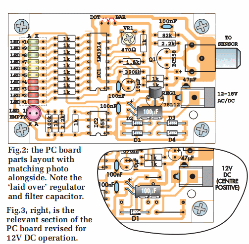
A 12V supply with centre positive can be plugged into the power socket. In this case, regulator REGl and diodes D2, U3 and D4 can be omitted. Both D4 and REGl are then replaced by wire links - ie, install a link instead of D4 and install a link between the IN and OUT terminals of REGl. These changes are shown in Fig.3.
Diode Dl should remain in circuit to protect against reverse battery connection. Or at the expense of another half-volt or so (which shouldn't cause any problems), D1-D4 can be left in situ and then it won't matter which polarity the power connector uses. Regulator REGl is still omitted in this case.
Also, with a known 12 V supply (ie, one which doesn't rise markedly above 12 V), the 100|iF capacitor can be changed to a cheaper (and smaller) 16V type.
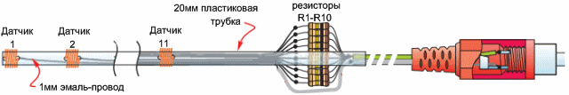
Fig.4: an 'x-ray' view of the sensor assembly, built into a 2.4m length of 20mm PVC electrical conduit.
Construction
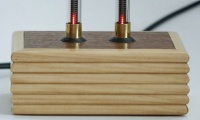
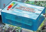
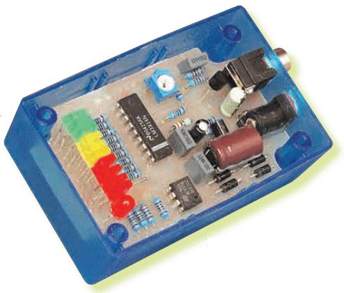
Construction is fairly straightforward, with all the parts installed on a PC board, code 701, measuring 80 x 50mm. This board is available from the EPE PCB Service. The board is installed in a standard UB5-type (83 x 54 x 31mm) plastic case, with the LEDs all protruding through the lid. We happened to use one of the translucent blue types (because they look smart!) but they also come in black, grey and clear.
Before fitting any components to the PC board, you'll probably need to modify it by cutting the four inwards-rounded corners which accommodate the pillars in the case. The easiest way to do this is to drill out the four corner holes with a much larger drill (say 8mm) then cutting from each of the edges of the board to the hole edges.
We also found that our board was slightly oversize (by perhaps 2mm) to fit into the plastic case, but a couple of minutes with a file soon took care of that. Check to see that your board is a neat (friction) fit in the top of the case. Don't worry about the holes for the power and sensor plugs - we'll do those later.
Fig. 2 shows the topside component layout on the PC board. The underside copper foil master pattern is shown (full-size) in Fig. 5.
Begin construction by installing the resistors (and the single link at the bottom of the LED ballast resistors), diodes and capacitors (with the exception of the 100|iF electrolytic), then install transistor Ql and the ICs (but not the regulator). Make sure that the diodes and ICs are installed the right way around. The same applies to the electrolytic capacitors - be sure to install each one with its positive lead oriented as shown in Fig. 2.
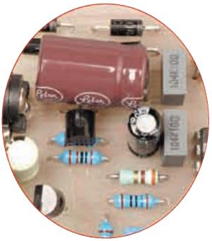
While the circuit calls for a 100|iF 35 V electrolytic as the main smoothing capacitor, these are now fairly hard to get and you may be forced to use a physically larger 100|iF, 50V version instead.
The only way this is going to fit (and allow the LEDs to poke through the case lid) is to lay it on its side. This, in turn, means that the 3-terminal regulator (REGl) also needs to be installed almost flat with its legs under the capacitor (you can see what we mean from the photos).
Trimpot VR1 can now be installed, followed by the RCA phono socket and the 2.5mm power socket. The two sockets are both PC-mounting types and mount directly on the board.
The LEDs are fitted last and must be installed so that the top of each LED is 15 mm above the PC board. This ensures that the LEDs all just protrude through the lid when the board is mounted in the case. Make sure that all LEDs are correctly oriented- the anode (A) lead is the longer of the two. Note that there are four holes provided for each of the LEDs - you need to use the innermost pairs of holes.
It's not particularly easy to get ten LEDs all aligned and at the same height. We cheated a bit by sticky-taping the reds, greens and yellows together as sets, aligning those three sets and then soldering them in. The pads on the board are arguably a little close together to fit standard rectangular LEDs without splaying their legs a little, but they can be made to look good.
Dot operation
As mentioned earlier, you can easily convert the LM3914 (ICl) from bar to dot operation if that's what you prefer. All you have to do is cut the thinned section of copper track between two pads immediately above and to the left of the trimpot.
If you want to get really clever, a miniature single-pole, two-position switch can be installed in place of the cut link (ie, between the two pads) so you can switch between bar and dot modes at will. This can be arranged so that it emerges through the case lid.
Checking it out
If a visual check confirms that you have all components in the right way and there are no solder bridges or dry joints, set trimpot VR1 to mid-way and plug in the power lead. If all is OK, the 'tank empty' LED should light, but all the others should remain unlit.
If the reverse happens, adjust the pot so that the 'tank empty' LED lights and all others are off.
Now lick your finger and press hard on the two solder joints (ie under the PC board) of the sensor connector, CONl. You should be rewarded with one or more lit LEDs in the string (with the 'tankempty' LED going out). The harder you press, the more LEDs should come on. You are, of course, simulating the resistor sensor string with your wet finger. The harder you press, the lower the resistance - and the more LEDs will light.
Final assembly
The PC board is designed to snap into the purpose-designed locators in the vertical ridges on the side of the case. However, first you need to drill two holes in one end of the case, so that they line up with the RCA phono socket and the power socket when the board is installed (see Figs.6 and 7).
You should onlv introduce the PC board to these holes and the ridge gaps after the PC board is working properly and set up because once in, it's very difficult to get out again!
There is one 5mm hole to be drilled here (for the 'tank empty' LED), along with a 25 x 5mm slot for the ten bargraph LEDs. The front-panel artwork (Fig.6) can be photocopied and glued to the case lid.
Sensor assembly
The sensor assembly is made by threading 10 lengths of lmm enamelled copper wire through 20mm OD PVC electrical conduit- see Fig.4. This conduit should be long enough to reach the bottom of the tank, with sufficient left over to fasten the top end securely. The reason for using lmm wire is primarily to make it easy to thread it through the conduit. Unfortunately, a single lOOg roll isn't quite enough for all ten sensors: you'll need part of a second roll.
The top sensor (Sll) is placed about 100 to 150mm below the overflow outlet at the top of the tank, while the other sensors are spaced evenly down the tube.
The distance apart is entirely up to you - depending on how accurate you want the readout and also, of course, the height of vour tank.
Begin by using a 1.5mm bit to drill holes through the tube wall at the appropriate points, including a hole for the bottom sensor (Si) to hold it in place securely. The holes should be angled up slightly to convince the lmm wire that this is the direction to head during the next step.
That done, you can thread the wires through by pushing them through the drilled holes and then up the tube. The end of each wire should also be smoothed before pushing it into the tube, to avoid scratching the enamel of the wires already in the tube. Leave about 250mm of wire on the outside of the tube at each point.
It's a good idea to trim each successive wire so that it protrudes say 20mm further out of the top of the tube than its predecessor. This will allow you to later identify the individual wires when attaching the resistors.
When all 11 wires have been installed, the next step is to solder the wire for sensor Si to the 'earthv' side of the figure-8 lead, cover it with insulating sleeving and pull the covered joint down about 50mm into the tube. This done, the resistors can be soldered to their appropriate wires.
Pushabout 15mm of 2.5mmsleeving over each wire before attaching its resistor. This sleeving should then be pulled up over the joint and the bottom end of each resistor after it is soldered. Once all the resistors have been soldered, the wires should be pulled down so that the joints are just inside the tube, as shown in Fig.4.
When this process is complete, there will be 10 resistors protruding from the top of the conduit. Their remaining leads are then twisted together, soldered to the other side of the figure-8 cable and covered with heatshrink tubing.
The other end of the figure-8 cable is fitted with an RCA phono plug, with the resistor lead going to the centre pin and the sensor 1 lead going to the earth side of the connector.
The next step is to scrape away the enamel from the 150mm wire lengths at each sensor point and wind them firmly around the outside of the tube. A 30mm length of 20mm copper water pipe can be pushed over sensor 1 to add weight and increase the surface area if desired.
On no account should solder be used on the submerged part because corrosion will result /ют galvanic action.
Finally, the end of the plastic conduit and the holes can be sealed with neutral-cure siliconesealant. However,don'tgetany silicone sealant on the coiled sensor wires, as this will reduce the contact area (and perhaps render them ineffective).
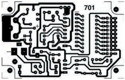
Fig.5: full-size copper foil PC board artwork.

Fig.6: front panel artwork. A photocopy of this may be used as a drilling template for the front panel.
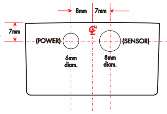
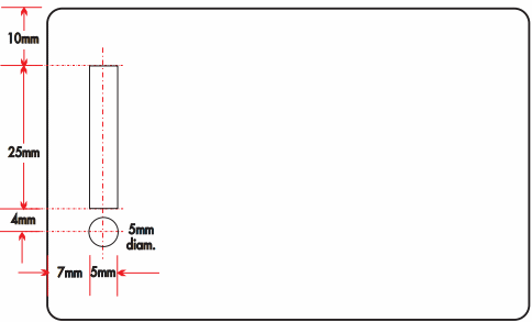
Fig.7: drilling detail for the box end (right) and box lid (far right). The slot can be made by drilling a row of 4.5mm holes down the centre line and enlarging with a small hie.
Switching on
Now for the big test. Apply power to the unit and check that the red 'tank empty' LED comes on and that there is +12 V on pin 3 of ICl. If all is well, the unit can now be tested by connecting the sensor assembly and progressively immersing it (starting with sensor 1) in a large container full of water (we used a swimming pool). When sensor 1 and sensor 2 are immersed, LED1 should extinguish and LED2 should come on.
Similarly, when sensors 1, 2 and 3 are immersed, LEDs 1 to 5 should be on and so on until all LEDs are lit.
Finally, trimpot VR1 must be set so that the appropriate LEDs light as the sensors are progressively immersed in water. In practice, you should find the two extremes of the pot range over which the circuit functions correctly, then set the pot midway between these two settings.
Using it on metal tanks
If the tank is of made of metal, you can dispense with Sensor 1 and connect the tank directlv to the circuit ground. You must also ensure sensors 2 to 10 do not touch the walls of the tank. This can be done by slipping a length of 2 5mm-OD P VC conduit over the completed probe, securing it at the top so that the water inside can follow the level in the tank.
Controlling other devices
You could use this project to control something external - for example, a pump to refill the tank from a larger storage tank or reservoir, a siren or warning alarm, or perhaps to trigger a radio link to remotely warn, and so on. Provision has been made on the PC board for this: vou will note that each of the LEDs, with the exception of the 'critical level' LED, has another pair of pads associated with it
- these are intended to connect to external circuitry.
The reason the 'critical level' LED has no extra pads is not simply lack of space
- we would imagine that any action you wanted to take would have happened long before the water level reached that critical point.
However, if you really wanted to, this level could also be used as outlined here for the rest of the LEDs - it's just that you'd have to arrange connections yourself.
As the LM3914 outputs go low to turn on their LEDs, these could also switch on a PNP transistor (with suitable current limiting resistors), leaving the LEDs in place. That transistor could be used to switch, say, a relay to control whatever you wished.
You could also switch an optocoupler, such as a 4N28, in parallel with the LEDs, itself perhaps switching a relay. With due care to power wiring, a triac optocoupler might be used instead.
Solidstate relays are also an option, providing you can get one which operates when its input is taken low. Of course, a transistor could invert the LM3914 output for you.
Regardless of what you are controlling, you MUST take into account the following:
• Get your project working as described (ie, stick to low voltages) before attempting to interface it to anything.
• Anything switching or controlling mains voltages must be more-than-adequately insulated, with cable clamps to prevent broken leads contacting anything else.
• Ensure that any relays you use are rated for both the voltage and the current of the device being controlled. Bear in mind that pump motors, for example, usually have a significantly higher starting current than running current.
EPE