
Матрица 8х8 от стереоканала
Схема управления матрицей светодиодов 8x8 или 16x16 с управлением от звукового входа воспроизводит случайный рисунок. Вход очень чувствительный.

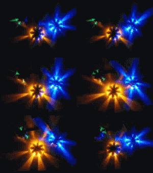
A A display based on the audio input will not be random. If the left and right channels of a stereo signal are applied to the X and Y inputs of a matrix, it will show the difference in the two signals. If the signal is mono, the display will be a 45 degree line that varies in length with the strength of the signal.
The LM3914 dot/bar graph LED driver is made for this application. The output is a current source so current limiting resistors are not needed. The 1С has 10 outputs but can be expanded to 20 or more. I will design an 8x8 matrix display to show how it works (Figure 1).
The input range is set by the reference voltage. In this case, I set it to one volt, assuming that the input would be line level. The 1/2 input pin is biased u\) I 2 w>lt so ih.it one volt p/p input will not clip. R4 and R6 set the current sink of IC2 at 10 mA. The current sink of IC1 is set at 1 mA and the current gain of the PNP transistors will keep them saturated.
An array of PNP transistors would be nice but the ULN series are all NPN. I found a four transistor PNP array for $6 but with 2N3906s at $.05, I went with singles. Pin 9 of the LM3914 is open for a dot display; you could connect pin 9 to Vcc for a bar display.
My schematic capture program (Eagle) does not do group copy of line drawings so I did not show all the diodes in the matrix.
NUTSandVOLTS January 2009
Robert Christopher



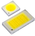
64 светодиода...