Преобразователь напряжения 9В в +12В и -12В
На английском...
Преобразователь напряжения 9В в +12В и -12В
Если надо получить +12V и -12V от 9-вольтовой батареи, то наша схема вам поможет.
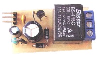
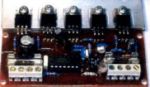
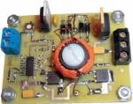
With switch-mode projects, there's always the problem of where to obtain inductors and/or transformers with the necessary specifications. Parts can be hard to find and expensive. So why not "roll your own?" In this project, we will design and wind a transformer and use it to get +12V and -12V from a 9V battery with the DC-to-DC converter shown in Figure 1.
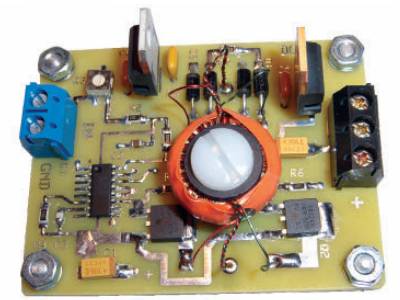
Рис.1
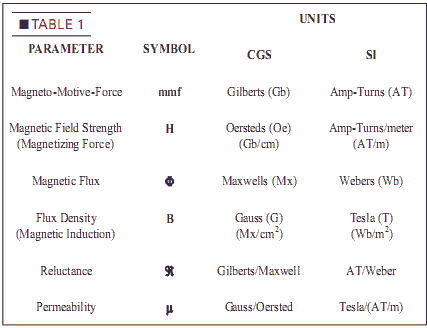
Many hobbyists who look into designing transformers go away thinking it's too hard. There are two reasons for that. First, magnetic material is non-linear, which leads to some arcane equations. Second, there's a profusion of magnetic terminology. There's one set of magnetic parameters, but two sets of units to describe them: cgs (centimeter-gram-second) and SI (Standard International). A third set is English units — is obsolete. We use SI units, but a conversion table is provided.
The switching circuit in this project is bare-bones.
Permeability, Magnetizing Force, and Flux Density
Like resistivity, permeability is a property of magnetic materials like iron. Unlike resistivity, permeability is not constant; it changes with flux. Actually, it changes with flux density (B).
Flux density is В - Ф/Ас and magnetizing force is H ¦ mint//). Since p changes with B, the B-H graph is non-linear as in Figure 3.
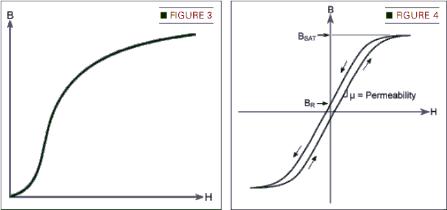
Permeability is the slope of the B-H curve at a specified value of В: рш AB/AH. As H increases beyond a certain point, the curve flattens out. That's saturation: the maximum flux density a given material can have.
Faraday's Law
In 1831, Michael Faraday showed that moving a coil through a magnetic field (or moving a magnetic field through a coil) induces voltage in the coil: V" М(ДФ/Д1) where:
V is the induced voltage.
N is the number of turns of wire in the coil.
ЛФ is the amount of magnetic flux the coil "cuts."
t is the amount of time the coils cuts through the flux.
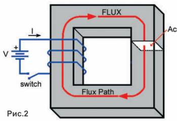
In Figure 2, closing the switch applies voltage across the coil. As coil current increases, mmf increases. Ф increases, and a voltage is induced in the coil that is equal but opposite to the applied voltage. The induced voltage lasts until the core saturates. Then, the coil becomes a short-circuit across the battery. So, the maximum At in the above equation is the time it takes for the flux to go from zero to saturation (sat). Saturation causes current spikes so the maximum flux used (Фш) must be less than Osat.
Hysteresis, Eddy Currents, and Power Loss
The B-H curve for magnetic material is more complicated than Figure 3. Apply a magnetizing force to a bar of steel. When you remove the mmf, the bar is magnetized with lesidual flux. To demagnetize the bar. you have to apply reverse mmf. If the battery in Figure 2 is replaced by an AC source, you g=t the B-H curve of Figure 4: a hysteresis loop. Every time the core flux cycles around the loop, some electrical energy gets converted into heat. It's a form of core loss. A changing magnetic field will induce voltage into any conductor it passes through, including the core itself. Voltage in the core causes eddy currents to flow producing l2R core loss. I2R in the coils is copper loss.
Ferrite vs. Steel
Both hysteresis and eddy current losses increase rapidly with frequency. At audio frequencies, transformer cores are made from insulated steel laminations. Steel has very high permeability, but a lot of loss at switch-mode frequencies where ferrite is used instead.
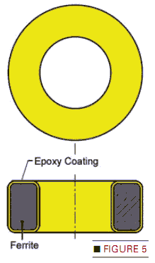
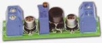
Ferrite is a ceramic containing iron and other elements. It starts as day-like material that can be formed into many shapes, then baked hard. It's brittle and can crack or break from too much mechanical stress. It has less permeability than steel, but much less bss at high frequency. Ferrite is conductive and abrasive, so often it's coated with insulation. Figure 5 shows a toroid core like the one we will use. A toroid is the ideal shape for a transformer core.
Voltage and Flux
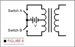
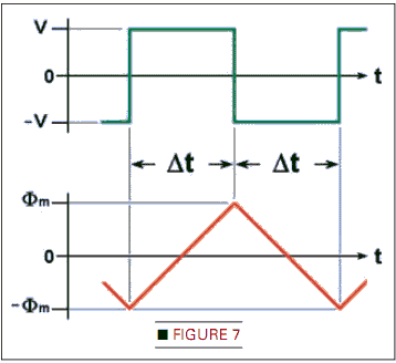
In Figure 6, the switches alternately open and close producing square wave voltage on the primary. Starting at t ¦ 0, flux increases according to Ф ¦ (V/N)t, producing triangle wave flux in the core as shown in Figure 7 (triangular as long as u doesn't change much with Ф). The current in the coil is also triangle wave.
Two points about Figure 7: First, flux goes from - Фт to + Фт, so Ф«2Фт Second, At is half the period, so At - T/2 -1/2f.
Turns per Volt
Rewrite Faraday's Law:
V-N(AO/At) - N(20m)/(1/2r) - 4NOm/
Rearranging terms yields an important parameter: the turns-per-volt (N/V). N/V - 1/(4Фпт/} But Фт -Вт х Ае. where Ae is the effective crass section area of the core, so:
N/V - 1 / (4 Вт Ае f).
Magnetizing Current (Im)
The flux linking primary to secondary in a transformer is generated by the primary mmf which is 90uout of phase with primary voltage as seen in Figure 7. Since Ф ж I, primary current is also 90° out of phase with primary \oltage so, except for losses, no power flows in. The primary looks like an inductor. The current in that inductor is the magnetizing current:
Hm - Bm/м => Nlm/fe - Bm/u => Im - (Bm /e)/uN
where ie is the effective length of the flux path. High im increases copper loss.
Rjtting a load on the secondary causes primary current to increase, but not flux in the core. The mmf caused by current in the secondary cancels mmf caused by the additional primary current, so there's no net change in flux.
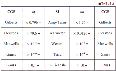
Terminology and Units
Table 1 shows the two sets of magnetic units. Table 2 shows how to convert from one to the other. The unit for mmf is actually just amps. The number of turns is a dimensionless multiplier.
Choosing a Core
We want a core that is efficient at 100 kHz with an internal diameter big enough so winding turns is easy. To minimize the number of turns, N/'V should be between 1 and 2.
The core chosen for this project is a FERROXCUBE TX16/9.1/4.7 epoxy coated toroid. The part number gives the dimensions: 16 mm OD, 9 mm ID, 5 mm thickness. It's made from their 3C90 ferrite material, designed for power applications up to 200 kHz. From its datasheet, Ae - 14.7 mm2 and le - 37.2 mm. Core loss at 100 kHz and 100 mT is less than 55 mW. Similar cores from other manufacturers like MAGNETICS and Fair-Rite would work also.
Bmax for 3C90 is about 350 milli-TesIa (mT) at 25°C. Using Bmax would lead to higher core loss and the danger of saturation. To be conservative, let Bm ¦ 100 mT. The turns per volt is:
N/V - 1/(4 Bm Ae/)
- 1/(4 • 0.1 • 14.7x10* • 1x1005)- 1.7 Calculate Np and Ns
Primary turns (Np) depend on primary voltage (Vp}. Np ¦ Vp x (N/V) - 9 x 1.7 - 15.3, which rounds off to 15.
The 7812 and 7912 regulators need 2.5 volts between input and output. Adding 2.5 to 12 gives 14.5 volts. Adding 0.5 volts for the cfrop across the Schottky rectifiers gives 15 volts. Another 0.5 volts for bss gives Vs ¦ 15.5 volts.
Secondary turns Ns - (Vs/Vp) x Np - (15.5 / 9) x 15 ¦ 25.8 which rounds up to 26. For a few less turns on the secondary, increase Bm a bit and recalculate N/'V.
Calculate Im
From the 3C90 specification sheet, u *4x10⁴ at В - 100 mT. So,
Im - (Bm fe)/pN
-(0.1 «37.2 10л)/(4 10л« 15) » 0.062 amps
Im = 62 mA is a reasonable value.
Winding the Transformer
This is the fun part. You need:
• Toroid core (1)
• Bifilar wire, 28 Ga., 42 inches
• Nylon screw (1), 10-32 3/4 inch
• Nylon nuts (2), 10-32
• Fiber washers (2), center-hole for #10 screw [optional]
Wind Primary and Secondary
We use bifilar wire: two strands of magnet wire glued together, with different insulation colors (e.g., red and g"een). It makes the center-tap very easy, but it's not available everywhere. Sources will be given in the Parts List.
You need 16 inches of wire for the primary and 26 inches for the secondary. Hold the core with the fingers of one hand. Put the primary wire through the core so that the short end forms a two inch lead; call it Lead 1. Use your thumb to hold the wire to the core.
With your other hand, fold a small loop in the long end close to the core and push it through the center (Figure 8). Grab the loop and pull the wire all the way through. (A small stick helps. The cosmetic department of your local drug store may have a cuticle stick — the perfect tool!). Bend the wire around the side of the toroid and put your thumb on the new turn to keep it from unraveling.
Repeat the process counting the turns. Distribute the turns more or less evenly. Space the turns so the last turn ends up next to the first turn. Leads 1 and 2 form the last turn. For example, Figure 10A shows 19 turns. When you g=t to the end, cut the remaining wire to make Lead 2 the same length as Lead 1. Lock the leads with three twists dose to the core (Figure 9).
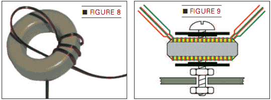
Lay four inches of plastic electrician's tape on a cutting surface. Cut the tape lengthwise into strips about 1/4 inch wide. Take a strip and wrap it over the primary turns as shown in Figure 9. To tell the primary from the secondary later on. tie a small piece of thread around the primary leads. Start winding the secondary 180° opposite of the primary leads using the same procedure. When done, tape the secondary as you did the primary.
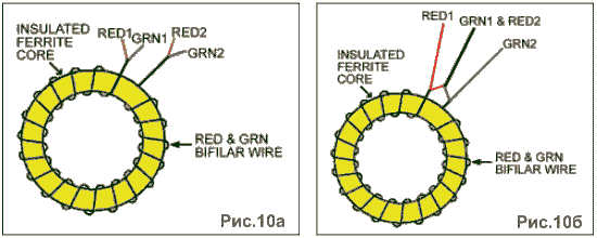
Form the Center-Taps
Use a sharp tool to split the ends of the primary leads. Peel apart the red and green wires (Figure 10A). Take the red wire from one lead and the green wire from the other lead and twist them tightly together to form the center-tap (Figure 10B). Repeat on the secondary leads.
Scrape about 1/4 inch of insulation off the center-tap (СТ) and the other wires of the primary. Tin the exposed copper ends. Repeat on the secondary wires. Use an ohmmeter to check continuity between CT and both wires of the primary; likewise for the secondary. Verify there is no continuity between primary and secondary.
Add the Hardware
Refer to Figure 9. Insert the nylon screw through a fiber washer. Insert the screw with the washer through the center of the toroid. Put the other washer on the screw and thread on a nut. Hand-tighten until snug. DO NOT OVER TIGHTEN. Figure 9 shows the transformer mounted on the circuit board using the second nut.
The transformer is done. Set it aside until needed.
Circuit Description
Figure 11 is the schematic of the converter. IC1 (LM3524) drives power MOSFETs Ql and Q2 which, in turn, drive the primary of the transformer in a square wave. Switching frequency is set by R4 and C3. The stepped-up voltage at the secondary is rectified and filtered to raw DC which is regulated down by IC2 and IC3. R7 prevents С 4 and C5 from charging up to the peak of voltage spikes that can occur with an unloaded secondary.
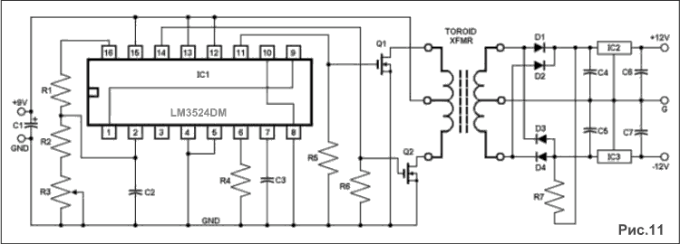
R5 and R6 are pull-downs to speed up the turn-off of Q1 and Q2. Since the MOSFETs turn on faster than they turn off, both transistors would be on for a part of every cycle if they switched simultaneously, causing the transistors to get hot from current spikes. To prevent that, the LM3524 provides dead time between turning off one transistor and turning on the other. Dead time is set by the voltage at pin 2, adjusted by trim-pot R3.
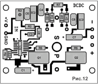
Construction
Figure 12 is the board layout. Components on the primary side are surface-mount (SMT) devices. (I'm using SMT since through hole parts are obsolete). The secondary side has mostly through-hole parts; I had a lot of the diodes and regulators, and wanted to use them.
There's an excellent video on soldering SMT devices on the Nuts & Volts Store page i.http:/.''store.nutsvolls.com; under the High Voltage Power Supply Circuit kit. I recommend viewing it before starting this project. Since the video is so thorough. I won't go into details about soldering here.
Mount IC1 -a 16 pin SOIC device — first. With a magnifier, carefully inspect the solder joints. Then, mount О, С2, C3. and C7. Check polarity on Cl and C7. Next, mount R1, R2, R4, R5, R6, R7, and trim-pot R3. Then mount Ql and Q2.
Mount Dl, D2, D3. and D4. Next, mount C4, C5, and C6. Then, mount IC2 and IC3. There are lines near the holes for IC2 and IC3 showing the positions of their metal tabs. Mount the two terminal blocks.
Before installing the transformer, connect the board to nine volts. Use an oscilloscope to look at the gates of Ql and Q2. You should see a square pulse with a rep-rate of about 100 kHz. Adjust R3 and verify that the pulse width varies. If it's working properly, set R3 for minimum pulse-width and disconnect power. If it's not working right, disconnect power and examine the solder joints on IC1. Verify that R4 and C3 are correct.
Mount the Transformer
Refer to Figure 8. Mount the transformer with the primary winding facing the P on the circuit board. (Remember that piece of thread you put on the primary?] Install the second plastic nut and hand-tighten it to the board. Clip off excess screw length. Insert the primary leads with the center tap going in the center of the three holes and solder them. Similarly, insert the secondary leads in their three holes and solder. Insulation on some magnet wire allows you to solder through it. If your iron is hot enough and you hold it on the wire long enough, the insulation will dissolve. Otherwise, you need to scrape it off.
Testing
Measure input current when you power up the board. If your supply has a current display, use it. If it doesn't, you can put а Ш resistor in series with the supply and get the current by measuring the voltage across it. (I got tired of replacing fuses in my DMM when using its current range.)
Apply nine volts to the board. If current jumps past 0.25 amps, remove power and examine the board again. Double-check polarity on C1 and C7. Verify IC2 and IC3 are installed correctly. Look for solder bridges. If you can't find the problem by inspection, you can always re-apply the power and see what gets hot or starts to Smoke. (I'm not kidding; IVe had to do that on several occasions.)
If the board passes the smoke test, verify that you have +12V and -12V on the outputs with no load. Then put a 220Q, HV resistor from each output to ground and verify that you still have +12V and -12V on the outputs. Use a voltmeter to measure the raw DC with and without a load. You'll see a drop with load. If the raw DC is too low with full load, you can increase it by adjusting R3.
Wrap-Up
The LM3524 requires 8V minimum and has a 40V maximum supply limit. Use the board as a platform to test your own transformer designs. Try making one that uses 12 volts input. Try making a step-down transformer to get +5V and -5V outputs (replace IC2 and IC3 with a 7805 and a 7905). You can eliminate the regulators and install jumpers at IC2 and IC3 to bring the raw DC to the output terminals. Have fun with it!